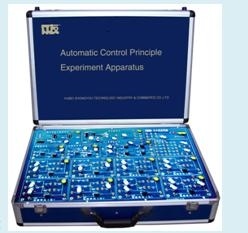
Automatic Control Principle Experiment Kit
I. Product Features (1) The system has perfect configuration, compact structure and self-equips many signal sources. Experiments could be made independently without need of external components (power signal generator etc); it could fully meet the teaching requirements. Teachers could research by these configuration and students could make course design by these configuration. (2) It adopts modular structure, which could construct simulation links and control system of various forms and orders, visualizes and simplifies experiment operation and equipment management. The experiment phenomena are clear and visual, which could deepen students’ understanding. A lot of high accurately devices are used in experiment apparatus so that the experiment phenomena are accurate and well accord with the principle. II. Performance Parameters (1) Input power: 220V~260 V, 50Hz (2) Output power: +5V/3A, +12V/1A, -12V/0.5A, -5V/0.5A (3) Input frequency: 47~63MHz (4) Output voltage/current: +5V/3A, +12V/0.3A, -12V/0.3A, -5V/0.5A (5) Output power: 35W (6) Efficiency: 75% (7) Adjustment performance: voltage regulation 0.2%
Load regulation 0.5% Ripple coefficient: 0.5% (8) External dimension: 450mm ×310mm×110mm III. System Composition (1) Operation simulation unit: includes eight groups of operation amplifier, resistance, capacitance, can form typical link of linear system: proportion (amplifying) link, integral link, inertial link, oscillation link, delay link, active advance lag link, etc. It can also flexibly and conveniently combine the system unit circuit by wire to form simulation link and control system of various forms and orders. (2) Signal source unit: can generate sine wave signal, and frequency and amplitude are adjustable. (3) Components unit: consists of several potentiometers, resistances, and capacitances. (4) Nonlinear unit: mainly used to research the characteristic of nonlinear unit. (5) Sample and hold circuit unit: include sampling circuit and holder circuit. (6) Power circuit unit: provide two groups of ± 12V/0.3A and ± 5V/0.15A constant voltage power output, ripple characteristic 5mV, as the electric power supply of automatic control circuit. (7) Equipped with locking wiring and experiment guidebook used for experiment. IV. Experiment Contents (1) Analog experiment of control system typical links (2) Typical second-order system transient response experiment (3) Typical third-order system transient response experiment (4) Testing experiment of typical link (or system) frequency characteristic (5) Dynamic characteristic experiment of PID controller (6) Series correction experiment of linear control system (7) Analog experiment of typical nonlinear link (8) Phase plane analysis experiment of nonlinear system (9) Pole configuration full-state feedback control analog experiment (10) Signal sampling and recovery experiment.
Click here!
Subscribe to:
Post Comments (Atom)

No comments:
Post a Comment